Electrochemical cells wear out. Light does not.
Most fixed and portable toxic-gas detectors use electrochemical (EC) cells. The chemistry is used up, so the cell is a consumable. For ammonia that is about one year of life, and about six months where the air carries a few ppm all the time (GfG application note AP1002). EC cells also cross-react: an NH₃ cell can read 35 ppm on 25 ppm H₂S, and its signal swings about ±40 % over −20…+50 °C (mPower TA-Note 4).
Electrochemical cell
- Small, cheap, low power
- Consumed by use; NH₃ cells ~1 year
- Cross-sensitivity, temperature drift
- Frequent bump tests and swaps
NDIR
- Stable, no consumables (our core, see IR·OEM)
- Broadband light, filter selects the band
- Not selective or sensitive enough for ppm-level NH₃, H₂S, HCN in a small can
TDLAS (laser)
- One narrow laser line per gas: selective, drift-checkable
- Built from discrete lasers, optics and long cells
- Analyzer size and cost, not a sensor part
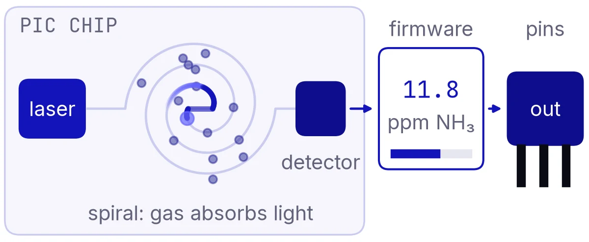
- 01 · Laser. An InP laser tuned across one absorption line of the target gas, in the near-infrared (1.51–1.58 µm). One laser technology covers all three toxic gases.
- 02 · Spiral. A long, low-loss waveguide coiled on a few mm². Gas that diffuses through the inlet absorbs a little of the light guided along it.
- 03 · Detector. A photodetector measures how much of the line is missing. More gas, deeper line.
- 04 · Firmware. Calibration and drift correction turn the line depth into ppm. The line itself is the reference, so zero can be checked without a gas bottle (target behaviour, to be shown on the bench).
- 05 · Output. In the drop-in format, a current that looks like an EC cell to the existing electronics, plus I²C / UART for the full reading and diagnostics.
H₂S is the exception: its near-infrared lines are too weak for direct absorption at alarm levels. Our route for H₂S is the same chip laser with a small photoacoustic / light-induced thermoelastic (LITES) cell; about 300 ppb has been shown in a 6×4×4 cm cell (Chen et al. 2023) published lab work.
Inside the can
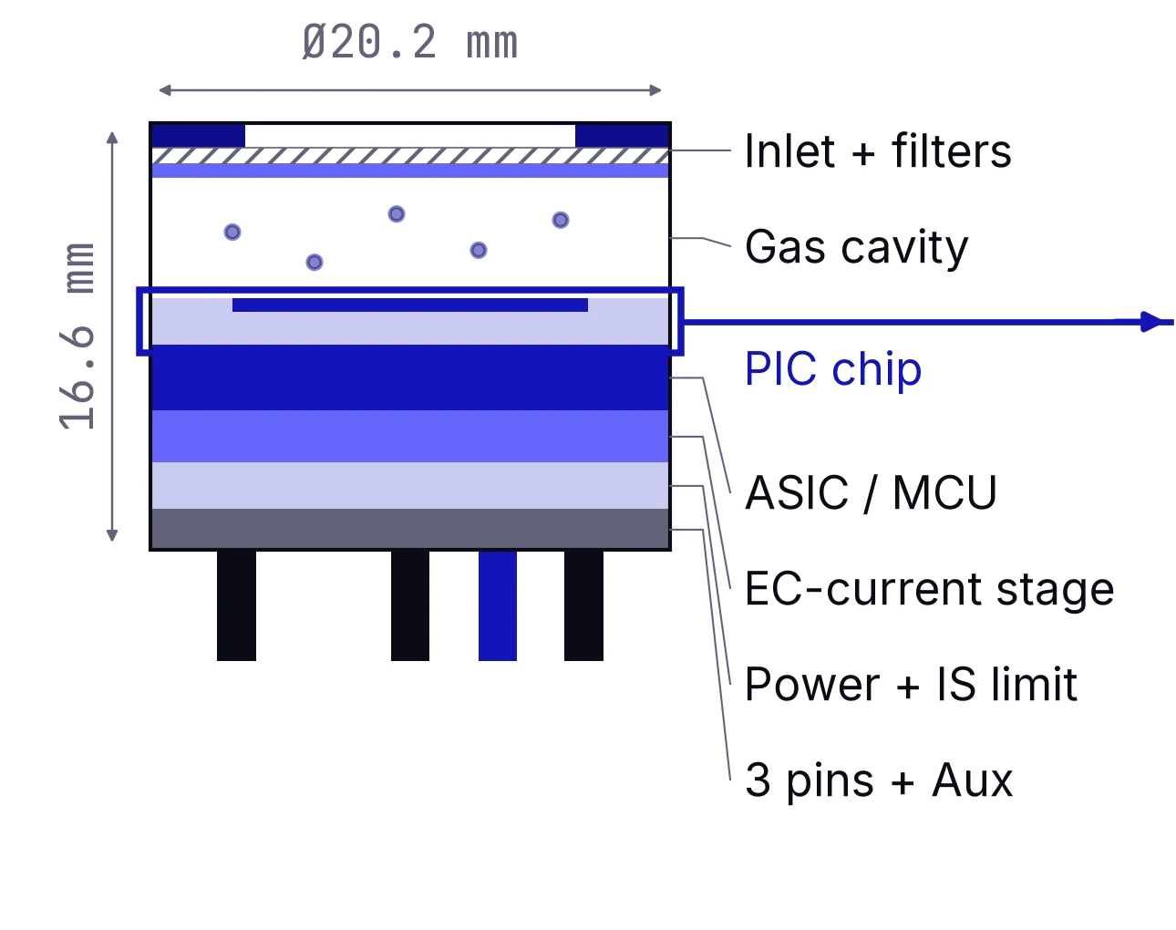
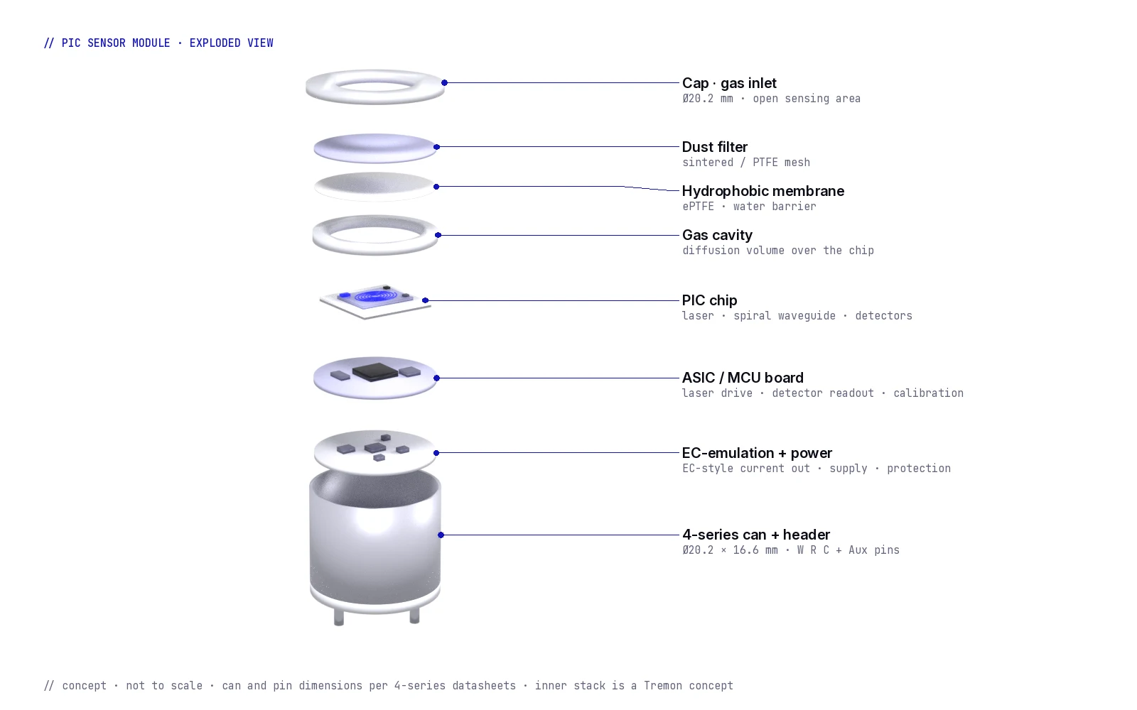
Exploded view of the module concept. The can and pin positions follow the 4-series datasheets; the stack inside is our design proposal, not a built part. No cooler (TEC): the laser is tuned by current and temperature.
Layers, top to bottom
- Cap · gas inlet: open sensing area, as on EC cells.
- Dust filter (sintered or PTFE mesh) and hydrophobic ePTFE membrane (water barrier).
- Gas cavity: a shallow volume over the chip; its size sets the response time.
- PIC chip on a ceramic carrier: laser, spiral waveguide, signal and reference detectors, temperature sensor.
- ASIC / MCU board: laser drive, detector readout, calibration memory, self-test.
- EC-emulation + power: EC-style current on W/R/C, supply regulation, protection.
- 4-series can + header: Ø20.2 × 16.6 mm, W, R, C and Aux pins on a 13.5 mm circle.
All concept. The H₂S photoacoustic cell would be an extra layer in an H₂S variant and is not shown.
Nothing on this page is a measured product specification yet. Each number is labelled: model estimate (Tremon calculation from HITRAN line data at an assumed noise floor), target (pass criterion we set for the bench and first chip), standard / datasheet (published values we design to), or published lab work (other groups).
| Item | Value | Status |
|---|---|---|
| NH₃ line | 1.514 µm (also 1.532 µm) | standard / datasheet HITRAN |
| NH₃ detection limit | ~1.5 ppm in 10 cm path · ~0.15 ppm in 1 m path | model estimate noise-equivalent absorbance 1e-5 |
| HCN line · detection limit | 1.528 µm · ~1.9 ppm in 10 cm · ~0.19 ppm in 1 m (≥ 1 m needed for the 0.9 ppm TWA) | model estimate |
| H₂S | ~1.578 µm; direct absorption does not reach 5 ppm → photoacoustic / LITES route | model estimate published lab work |
| Bench gate: detection limit at 10 s | ≤ ½ TWA: NH₃ 10 ppm · H₂S 2.5 ppm · HCN 0.45 ppm | target |
| Response time | t90 ≤ 150 s (standard limit); aim t90 ≤ 30 s | standard / datasheet target EN 45544 / IEC 62990-1 |
| Temperature | zero drift ≤ detection limit over −20…+55 °C | target |
| Format | 4-series can, Ø 20.2 mm × 16.6 mm, pins on 13.5 mm circle | concept dimensions per 4-series datasheets |
| Outputs | EC-compatible current on W/R/C + I²C / UART on pads | concept |
| Power | ~20–30 mW via one supply contact (EC sockets carry no power) | model estimate |
| Consumables | none in the light path | concept |
Same can, same pins: design it in, keep your product
We sell to OEMs, not to end users. The aim is a sensor that fits your existing detector platform with as little redesign as possible.
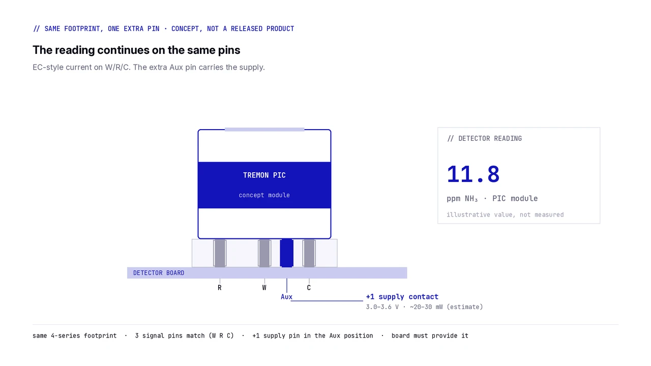
Same footprint, one extra pin
What a swap would look like on a board that has the fourth contact. Honest version: same can and the same three signal pins as a 4-series toxic cell, plus one supply pin in the Aux position. EC sockets carry no power, so the board must provide that contact.
| Cell (4-series) | Can | Pins | vs Tremon PIC module | Source |
|---|---|---|---|---|
| City 4CF+ (CO) | Ø20.2 × 16.6 mm | 3: W, R, C · Ø1.55 on 13.5 mm circle | W R C match · no Aux socket → board must add the supply contact | datasheet |
| City 4HN (HCN) | 4-series can | 3: sensing, reference, counter · Ø1.5 | W R C match · supply contact needed | datasheet |
| Honeywell 4NH3LL-100 (NH₃) | Ø20.2 mm, 4-series | 3: W, R, C · Ø1.5 on 13.5 mm circle | W R C match · supply contact needed | datasheet |
| SGX-4NH3 (NH₃) | 4-series can | 3: W, R, C · Ø1.5 on 13.5 mm circle | W R C match · supply contact needed | datasheet |
| Membrapor NH3/MR-100 (NH₃) | "Miniature" housing = 4-series | 3-electrode | W R C expected to match (pin drawing not checked) | datasheet |
| Alphasense CO-A4 / A4+ (CO) | Ø20.2 × 16.5 mm | 4: W, R, C + Aux electrode · Ø1.5 on 13.5 mm circle · A4+ adds I²C pads | W R C match · the Aux socket exists, but it reads an electrode, so the board must re-route it to a 3.0–3.6 V supply | datasheet |
| City 4OXV (O₂) | Ø20.4 × 16.6 mm | 2: anode, cathode + plastic locating pin | different pin set (2-electrode galvanic) · not a swap target | datasheet |
Plan, not commitments. Ammonia first, methane next, consistent with the rest of our photonics work.
- Done: line selection from HITRAN, detection-limit model, interface concept for the 4-series can.
- Not done yet: no chip has been made; no gas has been measured with it; no field data; no certification.
- Known hard parts: HCN needs a long path (≥ 1 m) for its exposure limit; H₂S needs the photoacoustic route; water and CO₂/CH₄ lines near 1.57–1.58 µm must be rejected.
- What we know well: gas detection hardware. Our NDIR products and field instruments are on the products page.
Building a detector that uses NH₃ or toxic-gas cells?
Tell us which gas, which can format and which electronics you use today. We are looking for detector makers to shape the interface and join the bench and alpha stages.